GSM Based Home Automation System Using SIM800L and Arduino Nano | Control Your Home Appliances From Anywhere | #homeautomation
Description
Hello, In today's article we are going to make an interesting project based on home automation. We use GSM technology to control home appliances from anywhere in the world. In this project, we use GSM SIM800L to make our project compact & its PCB will also be Compact. The whole appliances will get controlled through a single message sent by us to the GSM module. The message will be simple means the command, for example, if you want to turn on the light, you just need to send a message like (lighton) it's simple to handle. If you want to turn your home into a Smart Home you just need to install this set up in your home. which I'll explain to you in detail.
Imagine that you are coming from school or office and it's a very sunny day & you wish to your room will be cooled by AC before you reach to the home & think if you already implement this GSM based home automation setup in your home then you just need to send a message from smartphone to turn on your AC. This project is very useful to us to make our life easy. Our society needs this change if all peoples implement this set up in their home then it's possible to save a lot of energy.
If you are interested in electronics projects then subscribe to my youtube channel for more interesting projects.
GSM Module:-
In this project, we are going to use the SIM800L GSM module because it is very compact in size and hight efficient than the other GSM modules. This GSM module support quadband frequencies of 850MH \900MH \1800MH \1900MH.We can use this module to send SMS, Voice like a mobile phone.
Note:- This module takes a 3.8-4.3V DC power supply to run. You can also use an onboard Arduino 5V supply but using a 5V supply for a long time will burn/heat the module result in it damage the GSM module. Make sure that your power supply should be 2A more than 2A because this GSM module consumes lots of power while working.
But in this project, we going to power up the module with a 5V DC supply but it will damage Arduino so we use a Diode before powering the GSM Module. But I'm not going to use diode because we used LCD display, relays, and Arduino so the voltage gets divided so we can escape the diode.
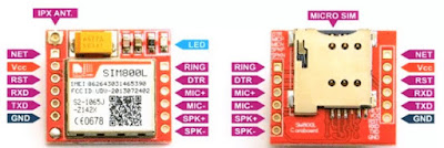
There is a LED on the GSM module, let's understand it.
1. When the module gets a power-up LED starts to blink.
2. When led blinks very fast with a 1-Second interval means SIM is not registered to the network.
3. When LED blinks slowly with a 3-Seconds interval means the SIM gets successfully connected to the network.
Pinouts of SIM800L GSM module :-
Working of the project:-
In this project, I'll explain to you how to make PCB by toner transfer method. When the system gets a power-up t the SIM800L starts to connect with the network. We can simply control the loads connected across the relays. To control the load we just need to Send SMS to the GSM module via a mobile phone. Suppose you want to control the bulb which is connected across Relay 1 you just need to send SMS ( load1on ) & the load will get turn on & you will get replay by GSM module ( Ok load 1 is On). It's simple to control the loads. If you want to know the status of the system then you need to send SMS ( load status ) then you will get the status message from the system on your mobile phone.
Material Required:-
(The following link are affiliated if you buy from the following link then we will get some bonus from them.)
- Arduino nano x 1:- (Buy Here)
- GSM module ( SIM800L ) x1:- (Buy Here)
- LCD Display (16x2) x1:- (Buy Here)
- Adapter (12V,2amp) x1:- (Buy Here)
- LM2596 module x1:- (Buy Here)
- Diode ( 1N4007 ) x 4:- (Buy Here)
- Relay SPDT (5V) x 4:- (Buy Here)
- DIP Switch (2Pin) x1:- (Buy Here)
- 2-Pin Block Connector x5:- (Buy Here)
- Copper Clad PCB Board (Single Side) x 1(8"x8") :- (Buy Here)
- Berge Strips x1:- (Buy Here)
- Transistor (BC547) x4 (Buy Here)
- 10k Potentiometer x1 (Buy Here)
- Solder Wire:- (Buy Here)
- Ferrite Chloride:- (Buy Here)
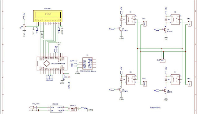
Circuit Diagram:-
Make proper connections as shown in the above circuit diagram. [ You can escape the D5 diode ]
PCB Layout:-
I design PCB layouts in EasyEda software. I provide the PCB layout link just print this layout on glossy photo paper with 100% accuracy / Actual Size. TO make PCB Using toner transfer method.
[PCB Layout] Click here to Download.
[Top Silk Layer] Click here to Download.
[Gerber File] Click here to Download.
Let's Make PCB:-
1. As you can see in the following Image I take a print of the PCB layout on glossy photo paper using toner filled laser printer.
2. First place the layout print on the PCB copper side, To transfer the tonner on PCB you can use an iron to transfer the toner from the glossy paper to PCB.Set iron to a high temperature & iron it for 10-15 minutes.
3. Take 2-3 teaspoons of ferrite chlorides in the tray to etch PCB, It will take 5-10 minutes to complete the etching process.
4. Now you can see a clean & clear PCB. Now it's time to drill PCB.
5. Now solder all components on PCB as shown in the following PCB 3D View.
6. Place all components as shown in the following 3D View of PCB.
Arduino Code:- [Download]
/*
   Hello guys welcome back to "Techno-E-Solution"
   Project Name:- GSM Based Home Automation System Using SIM800L and Arduino Nano
*/

#include<LiquidCrystal.h>
LiquidCrystal lcd(12,11,10,9,8,7);
#include <EEPROM.h>
#include <SoftwareSerial.h> //Create software serial object to communicate with SIM800L
SoftwareSerial GSM(2, 3);   //SIM800L Tx & Rx is connected to Arduino #2 & #3
String phone_no1 = "+91XXXXXXXXXX"; //change +91 with country code and XXXXXXXXX with phone number to sms
String phone_no2 = "+91XXXXXXXXXX";
String        RxString  = ""; // Will hold the incoming String  from the GSM shield
char          RxChar    = ' ';
int           Counter   = 0;
String        GSM_Nr    = "";
String        GSM_Msg   = "";
#define Relay1 A1 // Load1 Pin Out
#define Relay2 A2 // Load2 Pin Out
#define Relay3 A3 // Load3 Pin Out
#define Relay4 A4 // Load4 Pin Out
int load1, load2, load3, load4;
void setup(){ // put your setup code here, to run once
pinMode(Relay1, OUTPUT);
pinMode(Relay2, OUTPUT);
pinMode(Relay3, OUTPUT);
pinMode(Relay4, OUTPUT);
digitalWrite(Relay1, LOW);
digitalWrite(Relay2, LOW);
digitalWrite(Relay3, LOW);
digitalWrite(Relay4, LOW);
Serial.begin(9600);//Begin serial communication with Arduino and Arduino IDE (Serial Monitor)
GSM.begin(9600);   //Begin serial communication with Arduino and SIM800L
lcd.begin(16,2);
lcd.clear ();
lcd.setCursor (0,0);
lcd.print("GSM Based Device");
lcd.setCursor(0,1);
lcd.print(" Control System ");
delay(5000);
lcd.clear ();
lcd.setCursor (0,0);
lcd.print("Initializing....");
lcd.clear ();
Serial.println("Initializing....");
initModule("AT","OK",1000);                //Scan for GSM Module
initModule("AT+CPIN?","READY",1000);       //this command is used to check whether SIM card is inserted in GSM Module or not
initModule("AT+CMGF=1","OK",1000);         //Set SMS mode to ASCII
initModule("AT+CNMI=2,2,0,0,0","OK",1000); //Set device to read SMS if available and print to serial
Serial.println("Initialized Successfully");
//lcd.setCursor (0,0);
lcd.print ("System Is Ready");
delay (2000);
lcd.clear ();
lcd.setCursor (0,0);
lcd.print (" L1  L2  L3  L4 ");
//lcd.setCursor (0,1);
//lcd.print ("     Loads     ");

load1 = EEPROM.read(1);
load2 = EEPROM.read(2);
load3 = EEPROM.read(3);
load4 = EEPROM.read(4);
relays();
delay(100);
}
void loop(){
  RxString = "";
  Counter = 0;
  while(GSM.available()){
    delay(1);
    RxChar = char(GSM.read());
    if (Counter < 200) {
      RxString.concat(RxChar);
      Counter = Counter + 1;
    }
  }
  if (Received(F("CMT:")) ) GetSMS();
if(GSM_Nr==phone_no1 || GSM_Nr==phone_no2){

if(GSM_Msg=="load1on")
  {load1=HIGH; sendSMS(GSM_Nr,"Ok Load 1 is On");
  lcd.setCursor (1,1);
  lcd.print ("ON ");
  }
if(GSM_Msg=="load1off")
  {load1=LOW; sendSMS(GSM_Nr,"Ok Load 1 is Off");
  lcd.setCursor (1,1);
  lcd.print ("OFF ");
  }
if(GSM_Msg=="load2on")
  {load2=HIGH; sendSMS(GSM_Nr,"Ok Load 2 is On");
  lcd.setCursor (4,1);
  lcd.print (" ON ");
  }
if(GSM_Msg=="load2off")
  {load2=LOW; sendSMS(GSM_Nr,"Ok Load 2 is Off");
  lcd.setCursor (4,1);
  lcd.print (" OFF");
  }
if(GSM_Msg=="load3on")
  {load3=HIGH; sendSMS(GSM_Nr,"Ok Load 3 is On");
  lcd.setCursor (8,1);
  lcd.print (" ON ");
  }
if(GSM_Msg=="load3off")
  {load3=LOW; sendSMS(GSM_Nr,"Ok Load 3 is Off");
  lcd.setCursor (8,1);
  lcd.print (" OFF");
  }
if(GSM_Msg=="load4on")
  {load4=HIGH; sendSMS(GSM_Nr,"Ok Load 4 is On");
  lcd.setCursor (12,1);
  lcd.print (" ON ");
  }
if(GSM_Msg=="load4off")
  {load4=LOW; sendSMS(GSM_Nr,"Ok Load 4 is Off");
  lcd.setCursor (12,1);
  lcd.print (" OFF");
  }
if(GSM_Msg=="allon")
  {load1=HIGH, load2=HIGH, load3=HIGH, load4=HIGH; sendSMS(GSM_Nr,"Ok All Load is On");
  lcd.setCursor (0,1);
  lcd.print (" ON  ON  ON  ON ");
  }
if(GSM_Msg=="alloff")
  {load1=LOW, load2=LOW, load3=LOW, load4=LOW; sendSMS(GSM_Nr,"Ok All Load is Off");
  lcd.setCursor (0,1);
  lcd.print ("OFF OFF OFF OFF");
  }
if(GSM_Msg=="loadstatus")
{
String loadst = "";
if(load1==HIGH){loadst="Load1 On\r\n";}
        else{loadst="Load1 Off\r\n";}

if(load2==HIGH){loadst=loadst + "Load2 On\r\n";}
        else{loadst=loadst + "Load2 Off\r\n";}

if(load3==HIGH){loadst=loadst + "Load3 On\r\n";}
        else{loadst=loadst + "Load3 Off\r\n";}

if(load4==HIGH){loadst=loadst + "Load4 On";}
        else{loadst=loadst + "Load4 Off";}

sendSMS(GSM_Nr,loadst);
}
eeprom_write();
relays();
}
GSM_Nr="";
GSM_Msg="";
}
void eeprom_write(){
EEPROM.write(1,load1);
EEPROM.write(2,load2);
EEPROM.write(3,load3);
EEPROM.write(4,load4);
}
void relays(){
digitalWrite(Relay1, load1);
digitalWrite(Relay2, load2);
digitalWrite(Relay3, load3);
digitalWrite(Relay4, load4);
}
void sendSMS(String number, String msg){
GSM.print("AT+CMGS=\"");GSM.print(number);GSM.println("\"\r\n");
//AT+CMGS=”Mobile Number” <ENTER> - Assigning recipient’s mobile number
delay(500);
GSM.println(msg); // Message contents
delay(500);
GSM.write(byte(26)); //Ctrl+Z  send message command (26 in decimal).
delay(5000);
}
void GetSMS() {
  //Get SMS number
  GSM_Nr  = RxString;
  //get number
  int t1 = GSM_Nr.indexOf('"');
  GSM_Nr.remove(0,t1 + 1);
  t1 = GSM_Nr.indexOf('"');
  GSM_Nr.remove(t1);

  // Get SMS message
  GSM_Msg = RxString;
  t1 = GSM_Msg.indexOf('"');
  GSM_Msg.remove(0,t1 + 1);
  t1 = GSM_Msg.indexOf('"');
  GSM_Msg.remove(0,t1 + 1);
  t1 = GSM_Msg.indexOf('"');
  GSM_Msg.remove(0,t1 + 1);
  t1 = GSM_Msg.indexOf('"');
  GSM_Msg.remove(0,t1 + 1);
  t1 = GSM_Msg.indexOf('"');
  GSM_Msg.remove(0,t1 + 1);
  t1 = GSM_Msg.indexOf('"');
  GSM_Msg.remove(0,t1 + 1);
  GSM_Msg.remove(0,1);
  GSM_Msg.trim();
Serial.print("Number:"); Serial.println(GSM_Nr);
Serial.print("SMS:"); Serial.println(GSM_Msg);
}
// Search for specific characters inside RxString
boolean Received(String S) {
  if (RxString.indexOf(S) >= 0) return true; else return false;
}
// Init GSM Module
void initModule(String cmd, char *res, int t){
while(1){
    Serial.println(cmd);
    GSM.println(cmd);
    delay(100);
    while(GSM.available()>0){
       if(GSM.find(res)){
        Serial.println(res);
        delay(t);
        return;
       }
       else{Serial.println("Error");}}
    delay(t);
  }
  delay (500);
}
You can Buy me a coffee If you got this article helpful.


1 comment